What is P&ID?
A piping and instrumentation diagram, or P&ID, shows the piping and related components of a physical process flow. It’s most commonly used in the engineering field.
Function and purpose of P&IDs
P&IDS are foundational to the maintenance and modification of the process that it graphically represents. At the design stage, the diagram also provides the basis for the development of system control schemes, like Hazard and Operability Study (HAZOP).
For processing facilities, it’s a graphic representation of
- Key piping and instrument details
- Control and shutdown schemes
- Safety and regulatory requirements
- Basic start up and operational information
When to use P&IDs and who uses them
P&IDs are a schematic illustration of the functional relationship of piping, instrumentation and system equipment components used in the field of instrumentation and control or automation. They are typically created by engineers who are designing a manufacturing process for a physical plant.
These facilities usually require complex chemical or mechanical steps that are mapped out with P&IDs to construct a plant and also to maintain plant safety as a reference for Process Safety Information (PSI) in Process Safety Management (PSM). If something does go wrong, reviewing the P&ID is usually a good place to start. P&IDs are invaluable documents to keep on hand, whether they’re used to streamline an existing process, replace a piece of equipment, or guide the design and implementation of a new facility. With the record they provide, changes can be planned safely and effectively using Management of Change (MOC).
P&IDs are used by field techs, engineers, and operators to better understand the process and how the instrumentation is interconnected. They can also be useful in training workers and contractors.
What are P&IDs all about?
P&IDs play an essential role in the process engineering world to show interconnectivity, but they don’t necessarily include specifications. Specifications are usually provided in separate documents. But they are incredibly useful in many ways, including:
- Evaluate construction processes
- Serve as a basis for control programming
- Develop guidelines and standards for facility operation
- Produce documents that explain how the process works
- Provide a common language for discussing plant operations
- Create and implement philosophies for safety and control
- Design a conceptual layout of a chemical or manufacturing plant
- Form recommendations for cost estimates, equipment design, and pipe design
What’s the difference between a process flow diagram (PFD) and a piping & instrumentation diagram (P&ID)?
Instrumentation detail varies with the degree of design complexity. Simplified or conceptual designs are called process flow diagrams (PFDs). A PFD shows fewer details than a P&ID and is usually the first step in the design process–more of a bird’s eye view. More fully developed piping and instrumentation diagrams (P&IDs) are shown in a P&ID.
What are the limitations of P&ID?
Since P&IDs are graphic representations of processes, they have some inherent limitations. They can’t be relied on as real models, because they aren’t necessarily drawn to scale or geometrically accurate. There’s also no generally accepted universal standard for them, so they may look different from company to company—or even within the same company—based on internal standards, the type of software system being used, and the preferences of the creator. That’s why it’s important to design and review the documentation that gets down to the real nuts-and-bolts of support documents.
A look at P&ID support documents
Because P&IDs are schematic overview graphics, you need documents to clarify the details and specifications. Here are some of them:
-
Process flow drawings (PFDs)
. P&IDs originate from PFDs. A PFD is a picture of the separate steps of a process in sequential order. Elements that may be included are: sequence of actions, materials or services entering or leaving the process (inputs and outputs), decisions that must be made, people who become involved, time involved at each step and/or process measurements. -
Piping material specifications (PMS)
. Here’s where you find details about materials of construction, gaskets, bolts, fittings. -
Equipment and instrumentation specifications (EIS)
. Standards and details too extensive to fit into the P&ID are included in the EIS including Scope, Standards, Codes and Specifications, Definitions and Terminology, Materials of Construction, Design Basis, Mechanical/Fabrication, Guarantees, Testing and Inspection, Documentation and Shipping. -
Functional Requirement Specification (FRS).
How the plant or system operates is detailed in the FRS. It includes the Functional Description, Communication, and Scope Definition of the process.
What should a P&ID include?
While there are no exact standards for the way P&IDs should be drawn, there have been standards suggested by the Process Industry Practice (PIP), a consortium of process industry owners and engineering construction contractors who serve the industry. PIC001: Piping and Instrumentation Diagram Documentation Criteria details what a P&ID should contain:
- Mechanical equipment with names and numbers
- All valves and their identifications
- Process piping, sizes and identification
- Miscellaneous - vents, drains, special fittings, sampling lines, reducers, increasers and swagers
- Permanent start-up and flush lines
- Flow directions
- Interconnections reference
- Control inputs and outputs, interlock
- Seismic category
- Interfaces for class changes
- Quality level
- Annunciation inputs
- Computer control system input
- Vendor and contractor interfaces
- Identification of components and subsystems delivered by others
- Intended physical sequence of the equipment
- Equipment rating or capacity
What should a P&ID not include?
The nitty-gritty details can be better left to support documents. You want to create P&IDs that create clarity, not clutter. For that reason, you will want to omit:
- Instrument root valves
- Control relays
- Manual switches
- Primary instrument tubing and valves
- Pressure temperature and flow data
- Elbow, tees and similar standard fitting
- Extensive explanatory notes
Master the basics of Lucidchart in 3 minutes
- Create your first diagram from a template or blank canvas or import a document.
- Add text, shapes, and lines to customize your diagram.
- Learn how to adjust styling and formatting.
- Locate what you need with Feature Find.
- Share your diagram with your team to start collaborating.
How to Make a P&ID Diagram in Lucidchart
For the purposes of this guide, we’ll proceed as though you’re using Lucidchart. Lucidchart was created with P&ID diagrams in mind, so creating a useful diagram will be incredibly easy. Get started with a free Lucidchart account.
1. List equipment
Remember that P&IDs represent the hardware and software necessary to design, build, and run a process industry facility. To create such a comprehensive design, start by listing the elements in a standard P&ID. Your list should include all piping elements, including the order and placement of:
-
Branches
-
Control interlocks
-
Equipment
-
Instrumentation
-
Reducers
-
Valves
2. Add shapes
In your new Lucidchart account, open up a new document. You may need to enable the the Process Engineering shape library by clicking on the “Shapes” button on the upper left corner of your browser. Find the Process Engineering option and make sure the box has been checked.
Once the P&ID shapes are available to you, simply drag the necessary shapes onto the canvas and configure them by clicking the context panel icon that appears next to the shape. A variety of options appear here; for example, a tank can be customized with various roof types, and users can toggle between hiding and showing the stump. If you get lost in the vast array of P&ID shapes, use the toolbox’s search function to find a specific symbol.
3. Connect pipes and equipment
Now that you’ve assembled the components, connect them to each other in the appropriate order. In Lucidchart, each shape snaps cleanly to a connecting line or pipe. If you’re not sure how the process ought to flow, ask yourself:
-
Which action triggers this process?
-
What happens next?
-
To move onto the next step, what equipment do I need?
-
Does this unit require special configuration?
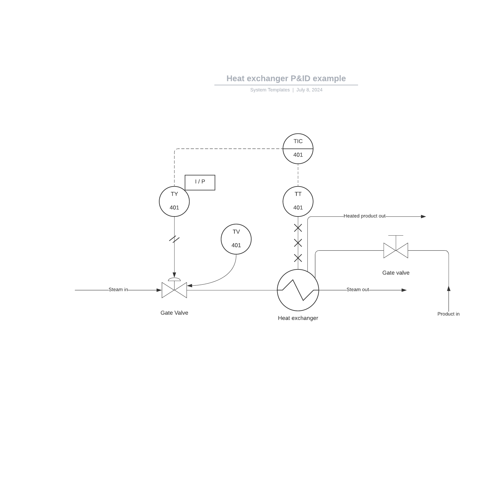
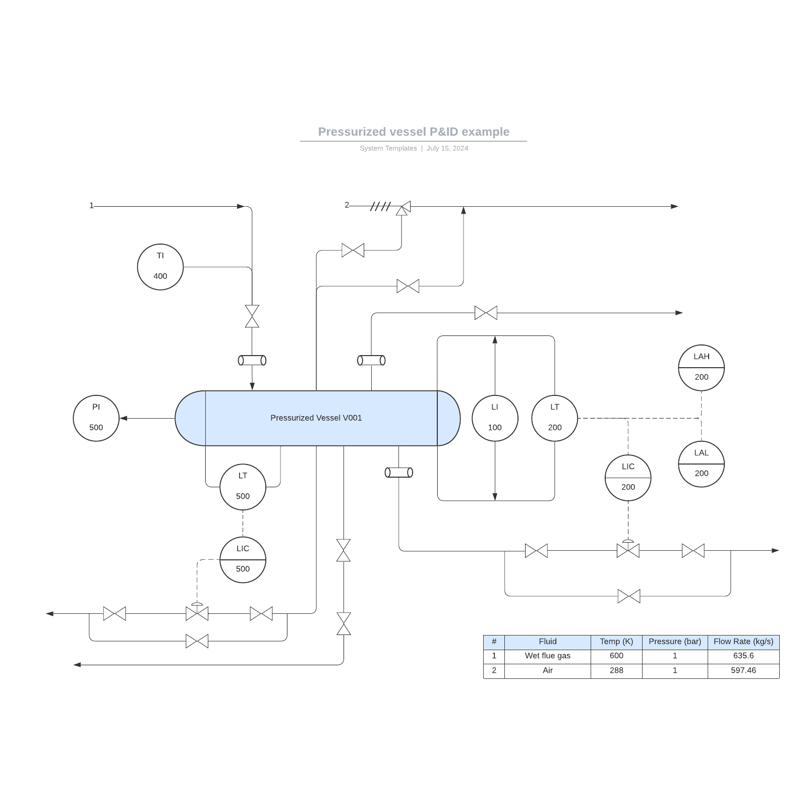
P&ID Examples & Templates
We understand that diagramming can be tricky at times, which is why Lucidchart has been built to include templates and examples that can help you to gain inspiration. Try out the following templates by clicking on the link below.
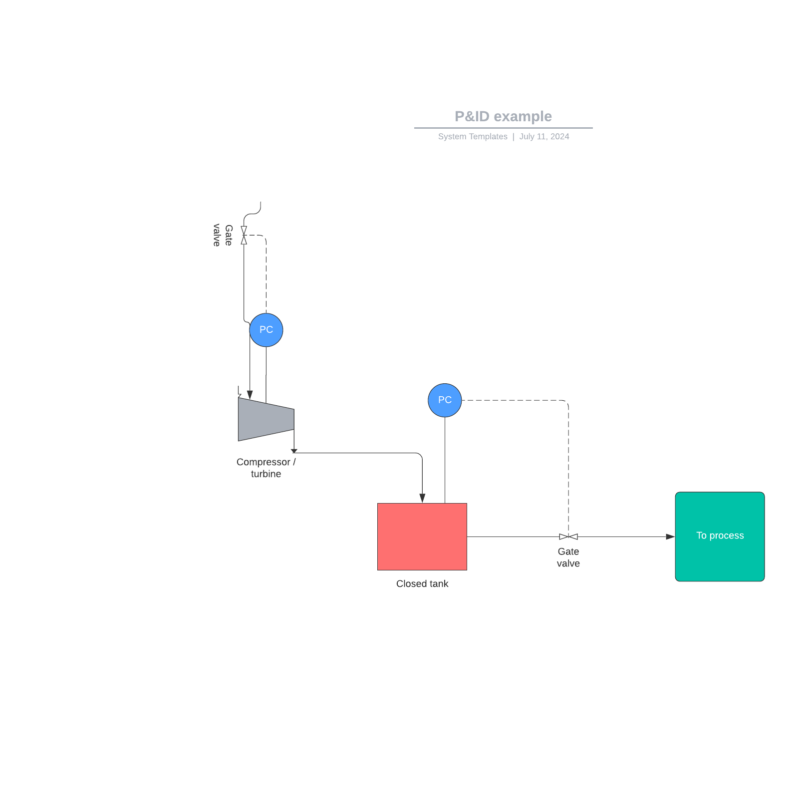
P&ID flow system example
Open this example to see a fluid flow system—this diagram defines the mechanical and design configurations that are in place. Try editing the elements to produce a more efficient process. Read more about P&ID examples.

P&ID separator vessel example
Check out our template for a P&ID of 3-phase separator vessels. These components are used in the oil and gas industry to separate various liquids that flow from oil wells. Try out Lucid's P&ID template.

How to create a P&ID
If you use software to create your P&IDs, there are some basic steps to follow:
- Create and check an equipment list. Use the symbols within the library after you’re sure of your list.
- Connect pipes and equipment, then review the details with a trusted colleague. Walk through the process several times and search for inefficiencies.
- Share with collaborators.
For more details about Symbols and Notation go to the P&ID Symbols Legend.
Organization fundamentals of P&ID
As a keystone document, the P&ID should be organized in a logical progression. While many—or most—companies set their own standards for P&ID organization, it can be thought of as chapters of a book or scenes from a movie that interconnect to tell your engineering process story. It should provide a concise and easy-to-understand illustration of all the equipment to be included in the process flow, alert information around hazard, safeguards and potential faults so that errors can be minimized or eliminated. It will help support the development of operating and maintenance procedures. As a storyboard of the process, it’s a way to see that changes can be made safely and effectively using Management of Change.
Different types of P&ID diagrams
There are as many different styles and types of diagrams as there are companies and products.
Piping & instrumentation shapes in Lucidchart
All of Lucidchart’s P&ID shapes and options are based on the ISA S5 standards. Within the application, they are categorized according to the following groups (which do not constitute a comprehensive list):
Equipment
-
Compressors
-
Conveyors
-
Motors
-
Turbines
Piping
-
One-to-many pipes
-
Multi-line pipes
-
Separators
-
Reducers
-
Flanges
Vessels
-
Vessels
-
Tanks
-
Cylinders
-
Columns
-
Bags
Heat exchangers
-
Boilers
-
Condensers
-
Exchangers
Pumps
-
Pumps
-
Fans
Instruments
-
Indicators
-
Transmitters
-
Recordings
-
Controllers
-
Elements
Valves
-
Valves
-
Rotameters
-
Orifices
What to look for in P&ID diagram software
There are lots of software tools that enable diagramming. But there are criteria that can make P&ID more efficient: ISA standards adherence, ease of use, ability to integrate into other productivity tools, and most importantly in many cases, the power to collaborate with other team members and departments.
Why is Lucidchart right for your P&IDs?
Lucidchart online flowchart maker is used by people around the world to create P&ID and many other types of diagrams and charts. Because of its intuitive user interface and collaborative features, it is the most popular online Visio alternative. Lucidchart was designed to be both intuitive and powerful to meet the needs of engineers, so projects go smoothly for everyone involved in your P&ID process:
-
Simple to use
: Detailed diagramming options for fast, precise drawing. And since Lucidchart's symbols are based on the ISA S5 standards, your P&IDs will be welcome in any professional context. Engineers and technicians will appreciate Lucidchart's streamlined online P&ID software. Drag-and-drop simplicity, keyboard shortcuts, and interactive elements make Lucidchart the perfect P&ID creator. -
Fully integrated
: Diagramming can fit seamlessly into your current workflow. Since Lucidchart is integrated with G Suite, Google Drive, JIRA, Atlassian, and other top productivity tools, all you need to do is plug and play. -
Enables collaboration
: Standard download options—PNG, JPG, PDF, VDX—or save the diagram to a secure webpage. Your diagram can also be embedded on any HTML website. Our cloud-based tool allows collaborators to work together for detailed, accurate work. To save time and energy, Lucidchart allows you to sketch out diagram requirements early on. Use our real-time collaboration—including group chat and commenting—while working with clients, engineers, and designers. -
Visio import/export
: Is your team still using Microsoft Visio to create piping and instrumentation designs? We offer the same shape set, but with a much friendlier price tag. Just import your old Visio documents into Lucidchart—they’ll become instantly editable.
A use case shows the value of Lucidchart—for everyone
It’s no small thing: Lucidchart can help save the earth. Ship ballast water is terrible for the environment. Its discharge usually includes non-native nuisance species that can cause extensive ecological and economic damage to aquatic ecosystems.
P&ID symbols and notations
One area of P&IDs that is standardized are the instrumentation symbols, the key to being able to understand P&IDs. Instrumentation symbols appearing on diagrams adhere to ANSI/ISA’s S5.1-1984 (R 1992) standards. Sticking to the Instrumentation, Systems, and Automation Society (ISA) S5.1 Instrumentation Symbols and Identification standard ensures a consistent, system independent means of communicating instrumentation, control, and automation intent so everyone understands.
ISA S5.1 defines four graphical elements—discrete instruments, shared control/display, computer function, and programmable logic controller—and groups them into three location categories (primary location, auxiliary location, and field mounted).
-
Discrete instruments are signified by circular elements
. Shared control/display elements are circles surrounded by a square. Computer functions are indicted by a hexagon, and programmable logic controller (PLC) functions are shown as a triangle inside a square. -
A single horizontal bar across any of the four graphical elements means the function resides in the primary location category
. A double line indicates an auxiliary location, and no line places the device or function in the field. Devices located behind a panel-board in some other inaccessible location are shown with a dashed horizontal line -
Letter and number combinations appear inside each graphical element and letter combinations are defined by the ISA standard
. Numbers are user assigned and schemes vary with some companies use of sequential numbering. Some tie the instrument number to the process line number. Others may choose to adopt unique and sometimes unusual numbering systems. -
The first letter defines the measured or initiating variables
. Examples inlcude Analysis (A), Flow (F), Temperature (T), etc. with succeeding letters defining readout, passive, or output functions such as Indicator (I), Record (R), Transmit (T), and so forth.
Here are some examples of P&ID symbols. You can review a full overview of all P&ID symbols included in Lucidchart if needed.
Equipment
Equipment is comprised of miscellaneous P&ID units that don't fit into the other categories. This group includes hardware like compressors, conveyors, motors, turbines, vacuums, and other mechanical devices.
Piping
A pipe is a tube that transports fluid substances. Piping can be made of various materials, including metal and plastic. The piping group is made up of one-to-many pipes, multi-line pipes, separators, and other types of piping devices.
Vessels
A vessel is a container that is used to store fluid. It may also alter the characteristics of the fluid during storage. The vessels category includes tanks, cylinders, columns, bags, and other vessels.
Heat exchangers
A heat exchanger is a device that's designed to efficiently transfer heat from different areas or mediums. This category includes boilers, condensers, and other heat exchangers.
Pumps
A pump is a device that uses suction or pressure to raise, compress, or move fluids in and out of other objects. This section is comprised of both pumps and fans.
Instruments
An instrument is a device that measures—and sometimes controls—quantities such as flow, temperature, angle, or pressure. The instruments group houses indicators, transmitters, recordings, controllers, and elements.
Valves
A valve regulates, directs, or controls the flow of a fluid by opening, closing, or partially obstructing passageways in a piping system. This category includes rotameters, orifices, and other types of valves.
You’ll find many more of the common shapes and symbols at Lucidchart P&ID Symbols Legend .