requirements modeling

Determining requirements for information systems projects

Reading time: about 8 min

Topics:

  • Leadership

An information system collects, stores, processes, analyzes, and distributes data. A well-designed information system can help your business be more efficient. And when you design a new information system, you should just jump right in without thinking about the system’s purpose or its requirements, right? 

Well, you could do it that way, but we wouldn’t recommend it.

It’s very important that you understand the system’s purpose and determine its requirements. Designing a system based on its requirements is much easier than going back and trying to fix things later.

In this article we’ll discuss the ways to plan and gather information for your projects.

Requirements modeling

There are a lot of different definitions for the word model. But generally a model is a representation of a thing or a system that you want to build. Models can help you to identify any potential problems that you might run into before investing too much time or money in building at full scale. So basically, a requirements model is a structured, visual representation of what needs to be included in your information systems projects.

Requirements modeling is critical to the success of your projects because:

  • It helps you develop processes to quickly deliver consistent products.
  • It helps the development team to have a better understanding of the product and processes.
  • You can give stakeholders and clients a detailed plan that addresses their specific requirements. 
  • It invites collaboration and rapid feedback that can decrease the risk of problems later on in the project.
  • It helps new team members to get a handle on the project so they have a better understanding of what their role is in the project.
  • It makes it easier to create simulations.
  • It lets you manage changing requirements requests.

Project planning and information gathering

So where do you start? How do you figure out what the requirements are, and how do you determine the purpose of your information system? Following are some steps that can help you to plan and gather information for your project. Following these steps can help you to find and fix problems faster, streamline development, and ultimately develop high-quality products on a consistent basis.

Determine the system’s purpose

Why are you designing the information system? What type of information will be stored? Understanding the purpose will help you make better decisions for your design. For example, you might be modeling a system for storing information such as customer ID and transactions, team members and skill sets, or service-level agreement contracts and renewal dates.

Starting with a written statement about what you want the system to accomplish makes the design and modeling process much easier. 

Gather information

You might want to start your information gathering by looking at existing data. You can analyze it to see what works well and what may need to be fixed. And you can determine what existing information can be used in your new system. Following are additional methods you can use to gather important information.

Brainstorming 

Bringing your team together for a brainstorm session lets your team solve problems and ideate in a creative way. Brainstorming gives every team member the chance to be heard. Sharing ideas and building on the ideas of others fosters better teamwork and cohesiveness. 

Lucidspark is a virtual whiteboard for bringing your team together for brainstorming sessions no matter where they are located. It encourages teamwork and real-time collaboration so you can turn ideas into actionable items.

requirements modeling
Reverse brainstorming (click on image to modify online)

Mind mapping

While brainstorming is more about generating a lot of ideas quickly, mind mapping is more about identifying a central concept and surrounding it with related ideas and information.

For example, the system’s stated purpose might be the mind map’s central idea. From there you draw branches and nodes that represent different system modules radiating out from the center. The branches show the relationship to the central idea as well as the relationships and concepts among the modules. Then you draw sub-branches that describe module functionality.  

Mind mapping is a free-flowing, creative approach to note-taking and outlining. It lets you document your thoughts with images and words and helps you to more clearly see and understand the relationships and connections among various concepts. 

A mind map is a visual representation of your thoughts that more closely resembles how your brain works. The images and colors used to create your mind maps help you to understand and retain information for a longer period of time. 

requirements modeling
Mind map (click on image to modify online)

Interviewing

Asking the people who will be using the system what they need, what they want, and what they expect to be able to do with data is an effective and relatively easy way to find out what requirements are needed. Working with stakeholders, clients, and decision makers will give you a better understanding of their needs so you can make better decisions as you determine requirements. Review your work with your stakeholders to discuss your understanding of what the information system will be, and to ensure that you are meeting needs and expectations. 

Identify entities, attributes, and relationships

Creating data model mockups can help you to organize data and define the relationships among data elements. Data modeling is a technique used to create a visual representation of your company’s business data, how it’s organized, and how it flows by analyzing and determining the data requirements.    

Data mockup modeling is important because it gives you the following benefits:

  • Cuts costs and reduces time to market
  • Improves business processes and streamlines development, ensuring consistent and high-quality product releases
  • Reduces complexities and risks
  • Improves collaboration among various teams and stakeholders

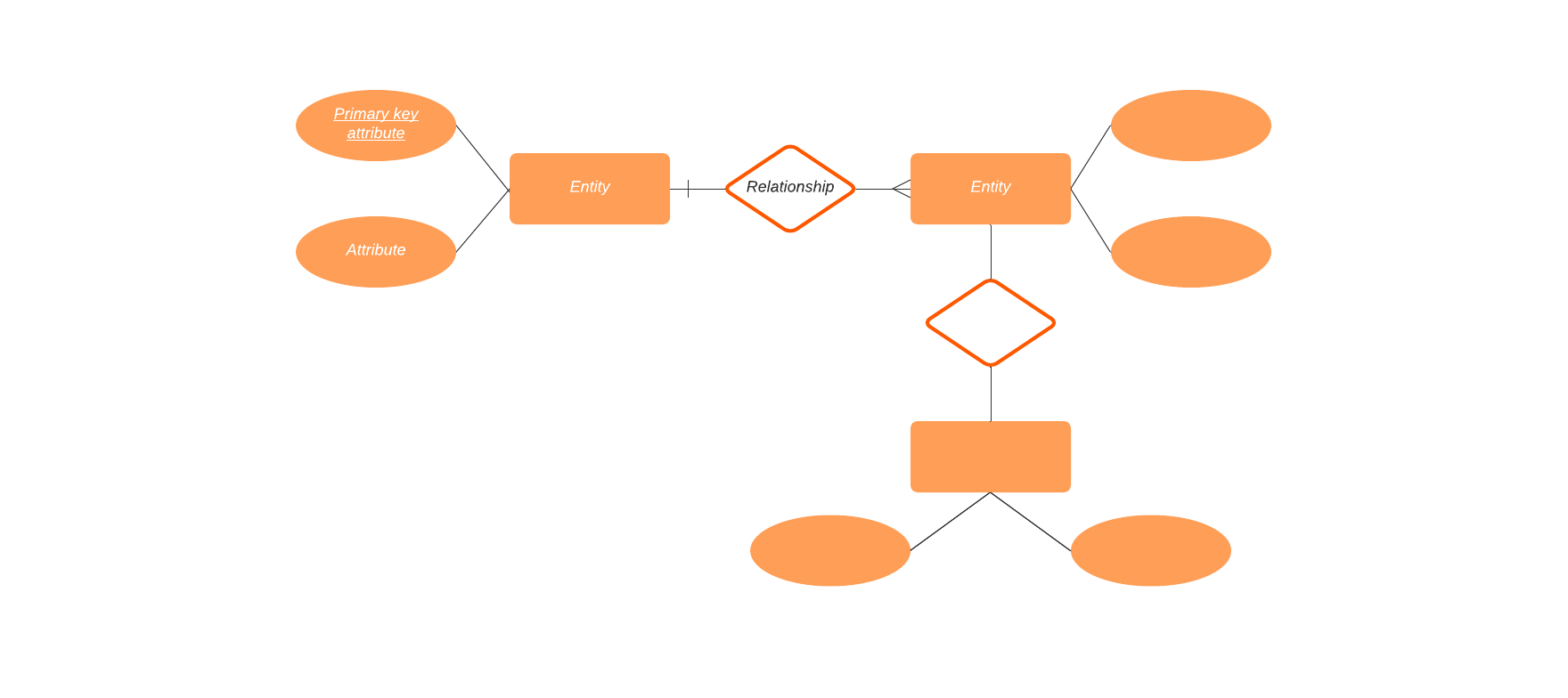
Create an ER diagram

An ER diagram is similar to a data flow chart. You use ER diagrams to document and illustrate the logical structure of your database, and to show how pieces of data (entities) relate to each other in your system. 

Think of an entity as a noun. It is something that has data stored about it. For example, a customer or a pizza. Entities have attributes that define characteristics belonging to each entity. For example, the name of the customer entity and the type of pizza entity (cheese, pepperoni, combo, etc.). 

Entities can be put into entity sets—a collection of entities that share the same attributes but might have different values for some of the attributes. For example, you might put a lot of Student entities in one set, but the value for each Name attribute will be different.

After you have defined the entities and attributes, it’s time to identify and define the relationships. A relationship describes the connection or association between one or more instances of entity types. Relationships can be thought of as verbs or verb phrases. For example, the customer’s name is Bob. Customer Bob bought a pepperoni pizza.

But you aren’t simply showing a relationship between two entities. You need to define what type of relationship it is. We’ll use entity sets A and B as an example:

  • One-to-one: One record in A corresponds to one record in B. For example, a student might be registered in a Physics of Sound and Acoustics course. The student might be enrolled in several different courses but only one Physics of Sound and Acoustics course.
  • One-to-many: One record in A corresponds to many records in B. For example, a single car company produces many different car models. But a specific model is built only by a specific car company.
  • Many-to-one:  Many records in A correspond to at most one record in B. For example, many different students have enrolled in one Physics of Sound and Acoustics class. 
  • Many-to-many: Many entities in A correspond to many entities in B. For example, many different car companies build many different car models.

ER diagrams use shapes like rectangles, ovals, and diamonds—similar to the shapes you might see in a flowchart—to represent different types of entities, their attributes, and relationships.  Specific lines are used to describe entity connections and cardinality (for example relationships that can be described as one-to-one, one-to-many, many-to-many, and so on). 

The benefits of creating ER diagrams include:

  • They are easy to understand and are useful for communicating requirements and architecture with developers, customers, stakeholders, and end users no matter how technical or non-technical they might be.
  • They help you to understand relationships between entities which can help you to find ambiguities or unnecessary processes.
  • ER diagrams translate into relational tables which can help you to build databases more quickly.
  • Database developers can use the diagrams as blueprints for implementing data in software applications.
  • They can be useful in other contexts such as describing relationships within an organization.
requirements modeling
ER diagram (click on image to modify online)

Drafting a requirements document

Everything you have done to this point will help you to determine what the requirements are for your project. The requirements document establishes the project’s purpose and summarizes the requirements. It also includes any mockups and models that have been built. 

When you write a requirements document, use language that is easy for everybody to understand. Don’t use jargon that might confuse your intended audience. Not everybody who will use this document will be skilled technically.

Be sure to review the document with stakeholders and subject matter experts to ensure that it is correct and includes everything that is needed.

requirements modeling

Use Lucidchart to create ER diagrams.

Get started for free

Lucidchart

Lucidchart, a cloud-based intelligent diagramming application, is a core component of Lucid Software's Visual Collaboration Suite. This intuitive, cloud-based solution empowers teams to collaborate in real-time to build flowcharts, mockups, UML diagrams, customer journey maps, and more. Lucidchart propels teams forward to build the future faster. Lucid is proud to serve top businesses around the world, including customers such as Google, GE, and NBC Universal, and 99% of the Fortune 500. Lucid partners with industry leaders, including Google, Atlassian, and Microsoft. Since its founding, Lucid has received numerous awards for its products, business, and workplace culture. For more information, visit lucidchart.com.

Bring your bright ideas to life.

Sign up free

or continue with

Sign in with GoogleSign inSign in with MicrosoftSign inSign in with SlackSign in

Get started

  • Pricing
  • Individual
  • Team
  • Enterprise
  • Contact sales
PrivacyLegal

© 2024 Lucid Software Inc.