Using Lucidchart, a collaborative visual workspace, you can customize easy-to-understand UML interaction diagrams that capture the dynamic behavior of your entire system.
Keep reading to learn the essentials of interaction diagrams, including how they’re used, how they can benefit you, and how to create one.
8 minute read
Do you want to create your own UML diagram? Try Lucidchart. It's fast, easy, and totally free.
What is an interaction diagram?
As its name might suggest, an interaction diagram is a type of UML diagram that's used to capture the interactive behavior of a system. Interaction diagrams focus on describing the flow of messages within a system, providing context for one or more lifelines within a system. In addition, interaction diagrams can be used to represent the ordered sequences within a system and act as a means of visualizing real-time data via UML.
Benefits of using an interaction diagram
Interaction diagrams can be implemented in a number of scenarios to provide a unique set of information. They can be used to:
- Model a system as a time-ordered sequence of events.
- Reverse- or forward-engineer a system or process.
- Organize the structure of various interactive events.
- Simply convey the behavior of messages and lifelines within a system.
- Identify possible connections between lifeline elements.
Types of interaction diagrams in UML
Interaction diagrams are divided into four main types of diagrams:
- Communication diagram
- Sequence diagram
- Timing diagram
- Interaction overview diagram
Each type of diagram focuses on a different aspect of a system’s behavior or structure. Take a look below for more information on the basics of each diagram and how you can benefit from them.
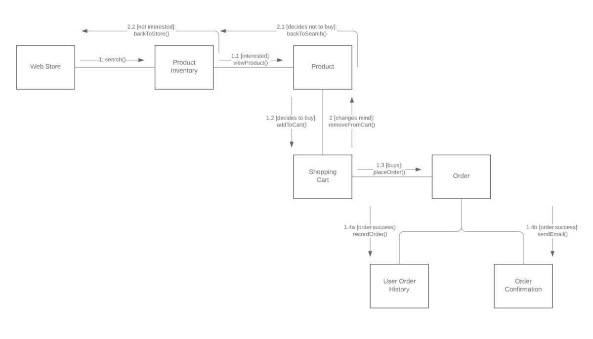
Communication diagram (or collaboration diagram)
In UML, communication diagrams depict the relationships and interactions among various software objects. They emphasize the structural aspects of an interaction diagram, focusing on object architecture rather than the flow of messages.
A communication diagram provides the following benefits:
- They emphasize how lifelines connect.
- They focus on elements within a system rather than message flow.
- They provide an added emphasis on organization over timing.
Communication diagrams can also have these possible downsides:
- They can become very complex.
- They make it difficult to explore specific objects within a system.
- They can be time-consuming to create.
Sequence diagram
Another option for depicting interactions is using sequence diagrams. These diagrams revolve around five main events:
- Order placement
- Payment
- Order confirmation
- Order preparation
- Order serving
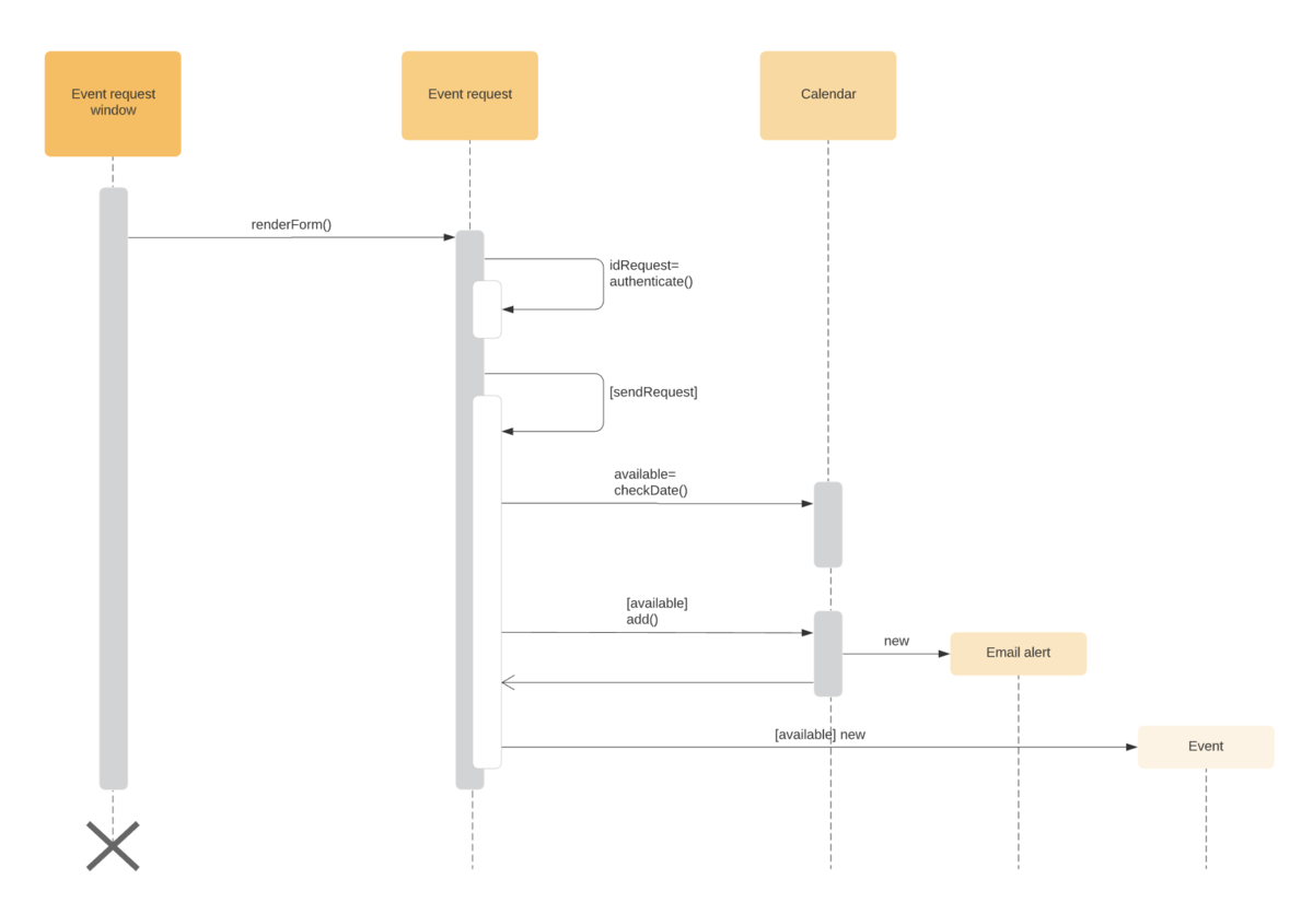
If the sequence of events changes, it can cause delays, or the system may crash. It’s important to select the notation that matches the particular sequence within your diagram.
A sequence diagram provides the following benefits:
- They’re easy to maintain and generate.
- They’re easy to update according to changes in a system.
- They allow for reverse and forward engineering.
Sequence diagrams can also have these possible downsides:
- They can become complex, with too many lifelines and varied notations.
- They’re easy to produce incorrectly and depend on your sequence being entered correctly.
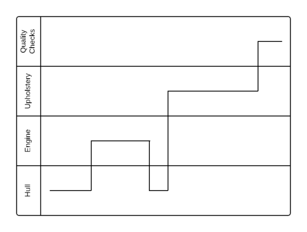
Timing diagram
Another diagram option can be to use timing diagrams. These are visuals used to depict the state of a lifeline at any instance in time, denoting the changes in an object from one form to another. Waveforms are used within timing diagrams to visualize the flow within the software program at various instances of time.
A timing diagram offers the following benefits:
- They allow for forward and reverse engineering.
- They can represent the state of an object at an exact instance in time.
- They can keep track of any and all changes within a system.
You should also consider these potential downsides of using a timing diagram:
- They can be difficult to understand.
- They can be hard to maintain over time.
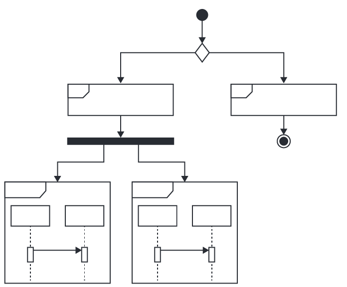
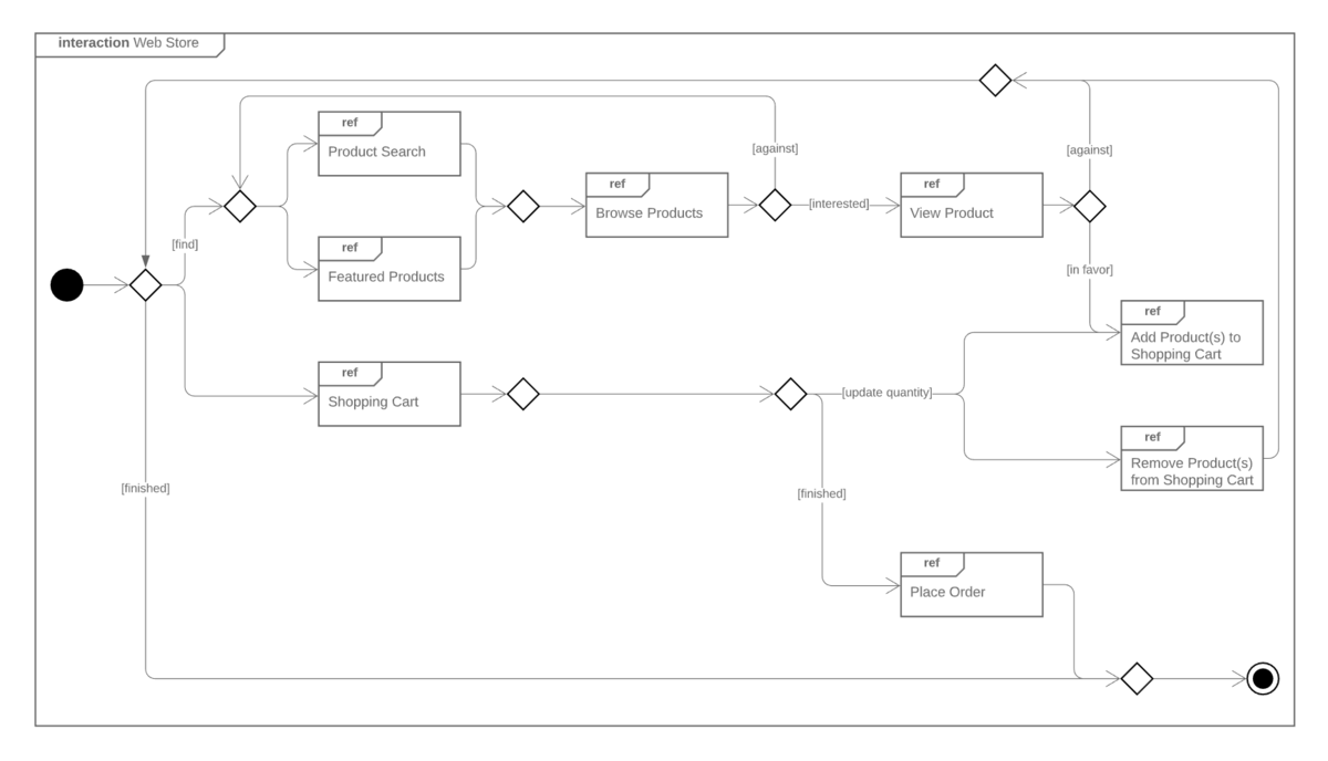
Interaction overview diagram
The interaction overview diagram provides a high-level view of an interaction model. The diagram acts as an overview of the flow of control from interaction to interaction, as well as the flow of activity from diagram to diagram.
A timing diagram offers the following benefits:
- They provide an uncomplicated view of the activity within a model.
- They offer a high degree of navigability between diagrams.
- They allow the use of most annotations within an activity diagram, along with additional elements for added clarity.
Although interaction diagrams are fairly intuitive, they do require branching and interactions to follow certain behaviors, which can be restrictive.
Do you want to create your own UML diagram? Try Lucidchart. It's fast, easy, and totally free.
Create a UML DiagramInteraction diagram symbols and terminology
Here are some common terms and symbols you’ll come across in an interaction diagram:
Lifeline: A lifeline depicts a single participant in a given interaction, describing how an instance of a specific classifier participates in an interaction.
The attributes of a lifeline are as follows:
- Name: Used to refer to the lifeline in a specific interaction. Lifeline names are optional.
- Type: Names the classifier of which the lifeline represents an instance.
- Selector: Used as a Boolean condition to select a particular instance that satisfies the requirement.
Message: A message is a specific type of communication between two lifelines in an interaction. It can be used to call an operation, create or destroy an instance, or send a signal. As lifelines receive and interact with messages, it creates a focus of control that moves from lifeline to lifeline. This is referred to as a flow of control.
The messages used within an interaction diagram are as follows:
- Synchronous message: The message sender keeps waiting for the receiver to return control from the message execution.
- Asynchronous message: The message sender continues the execution of the next message without waiting for a return from the message receiver.
- Return message: The receiver of a previous message returns the focus of control to the sender.
- Object creation: The message sender creates an instance of a classifier.
- Object destruction: The message sender destroys the created instance.
- Found message: The message sender is outside the scope of interaction.
- Lost message: The message is lost in the interaction and never reaches the destination.
Operator: An operator specifies how the operands will be executed within an operation. In UML, an operator supports operations on data in the form of branching and iterations.
The various operators within an interaction diagram are as follows:
- Opt (option): An operand is executed if the condition is true.
- Alt (alternative): An operand, whose condition is true, is executed.
- Loop (loop): This operator loops an instruction for a specific time period.
- Break (break): If the condition is true or false, the loop is broken, and the next instruction is executed.
- Ref (reference): This operator refers to another interaction.
- Par (parallel): All operands are executed in parallel with one another.
Branching: These are some of the most crucial terms in an interaction diagram. To represent branching within an interaction diagram, guard conditions are added to individual messages. These guard conditions are used to verify if a message can be sent forward or not. Only if a message’s guard conditions are true can it be sent forward. A message can have multiple guard conditions, and multiple messages can carry the same guard conditions.
Iteration: An interaction expression consists of an interaction specifier and an iteration clause. An iteration expression can also be used to show iteration expression in an interaction diagram. It involves no specific syntax.
Parallel iteration specifiers are used to show that messages are being sent in parallel. This is denoted by *//. In UML, iteration is achieved by using a loop operator.
State invariants and constraints: In an interaction diagram, a state is a situation or condition during a lifetime of an object—it satisfies a constraint, performs various operations, and waits for an event. A state can be changed when an instance or lifeline receives a message, though not all messages cause a change of state.
How to draw an interaction diagram
Follow these steps to ensure that you have the necessary information to begin creating your interaction diagram:
- Determine the scenario your interaction diagram will represent.
- Identify the lifelines that will be involved in your interaction.
- Explore each lifeline to identify potential connections and relationships, and then categorize your lifelines.
- Identify the sequence of message flows within your interaction.
- Identify the various types of messages within your interaction, as well as an ordered sequence of events and time constraints of each object.
- Within your UML diagram software, select the appropriate shapes, nodes, and lines to create the flow of activity within your diagram. Or, select a template and customize your diagram from there.
- Label each shape, node, and line to represent each event, interaction, and message within your system.
Note that your diagram’s design will vary when creating a sequence, timing, or communication diagram, as each diagram focuses on a different aspect of a system’s behavior.
Interaction diagram example
Here is a simple example of an interaction diagram template that can be used to model the interactions among the various elements of a basic web app. You can modify this template to visualize the control flow of a system and describe the interactions amongst objects within it.