
Sequence diagrams are a popular dynamic modeling solution in UML because they specifically focus on lifelines, or the processes and objects that live simultaneously, and the messages exchanged between them to perform a function before the lifeline ends. Along with our UML diagramming tool, use this guide to learn everything there is to know about sequence diagrams in UML.
6 minute read
Do you want to create your own UML diagram? Try Lucidchart. It's fast, easy, and totally free.
What is a sequence diagram in UML?
To understand what a sequence diagram is, it's important to know the role of the Unified Modeling Language, better known as UML. UML is a modeling toolkit that guides the creation and notation of many types of diagrams, including behavior diagrams, interaction diagrams, and structure diagrams.
A sequence diagram is a type of interaction diagram because it describes how—and in what order—a group of objects works together. These diagrams are used by software developers and business professionals to understand requirements for a new system or to document an existing process. Sequence diagrams are sometimes known as event diagrams or event scenarios.
Note that there are two types of sequence diagrams: UML diagrams and code-based diagrams. The latter is sourced from programming code and will not be covered in this guide. Lucidchart’s UML diagramming software is equipped with all the shapes and features you will need to model both. And with our diagram as code feature, it’s faster and easier than ever. You can create a custom sequence diagram on your Lucidchart document using Mermaid coding.
Benefits of sequence diagrams
Sequence diagrams can be useful references for businesses and other organizations. Try drawing a sequence diagram to:
-
Represent the details of a UML use case.
-
Model the logic of a sophisticated procedure, function, or operation.
-
See how objects and components interact with each other to complete a process.
-
Plan and understand the detailed functionality of an existing or future scenario.
Use cases for sequence diagrams
The following scenarios are ideal for using a sequence diagram:
-
Usage scenario: A usage scenario is a diagram of how your system could potentially be used. It's a great way to make sure that you have worked through the logic of every usage scenario for the system.
-
Method logic: Just as you might use a UML sequence diagram to explore the logic of a use case, you can use it to explore the logic of any function, procedure, or complex process.
-
Service logic: If you consider a service to be a high-level method used by different clients, a sequence diagram is an ideal way to map that out.
-
Sequence diagram Visio - Any sequence diagram that you create with Visio can also be uploaded into Lucidchart. Lucidchart supports .vsd and .vdx file import and is a great Microsoft Visio alternative. Almost all of the images you see in the UML section of this site were generated using Lucidchart.
Do you want to create your own UML diagram? Try Lucidchart. It's fast, easy, and totally free.
Create a UML DiagramBasic symbols and components
To understand what a sequence diagram is, you should be familiar with its symbols and components. Sequence diagrams are made up of the following icons and elements:
| Symbol | Name | Description |
|---|---|---|

| Object symbol |
Represents a class or object in UML. The object symbol demonstrates how an object will behave in the context of the system. Class attributes should not be listed in this shape. |

| Activation box |
Represents the time needed for an object to complete a task. The longer the task will take, the longer the activation box becomes. |

| Actor symbol |
Shows entities that interact with or are external to the system. |

| Package symbol |
Used in UML 2.0 notation to contain interactive elements of the diagram. Also known as a frame, this rectangular shape has a small inner rectangle for labeling the diagram. |

| Lifeline symbol |
Represents the passage of time as it extends downward. This dashed vertical line shows the sequential events that occur to an object during the charted process. Lifelines may begin with a labeled rectangle shape or an actor symbol. |

| Option loop symbol |
Used to model if/then scenarios, i.e., a circumstance that will only occur under certain conditions. |

| Alternative symbol |
Symbolizes a choice (that is usually mutually exclusive) between two or more message sequences. To represent alternatives, use the labeled rectangle shape with a dashed line inside. |
Common message symbols
Use the following arrows and message symbols to show how information is transmitted between objects. These symbols may reflect the start and execution of an operation or the sending and reception of a signal.
| Symbol | Name | Description |
|---|---|---|

| Synchronous message symbol |
Represented by a solid line with a solid arrowhead. This symbol is used when a sender must wait for a response to a message before it continues. The diagram should show both the call and the reply. |

| Asynchronous message symbol |
Represented by a solid line with a lined arrowhead. Asynchronous messages don't require a response before the sender continues. Only the call should be included in the diagram. |

| Asynchronous return message symbol |
Represented by a dashed line with a lined arrowhead. |

| Asynchronous create message symbol |
Represented by a dashed line with a lined arrowhead. This message creates a new object. |
|
| Reply message symbol |
Represented by a dashed line with a lined arrowhead, these messages are replies to calls. |

| Delete message symbol |
Represented by a solid line with a solid arrowhead, followed by an X. This message destroys an object. |
Sequence diagram examples
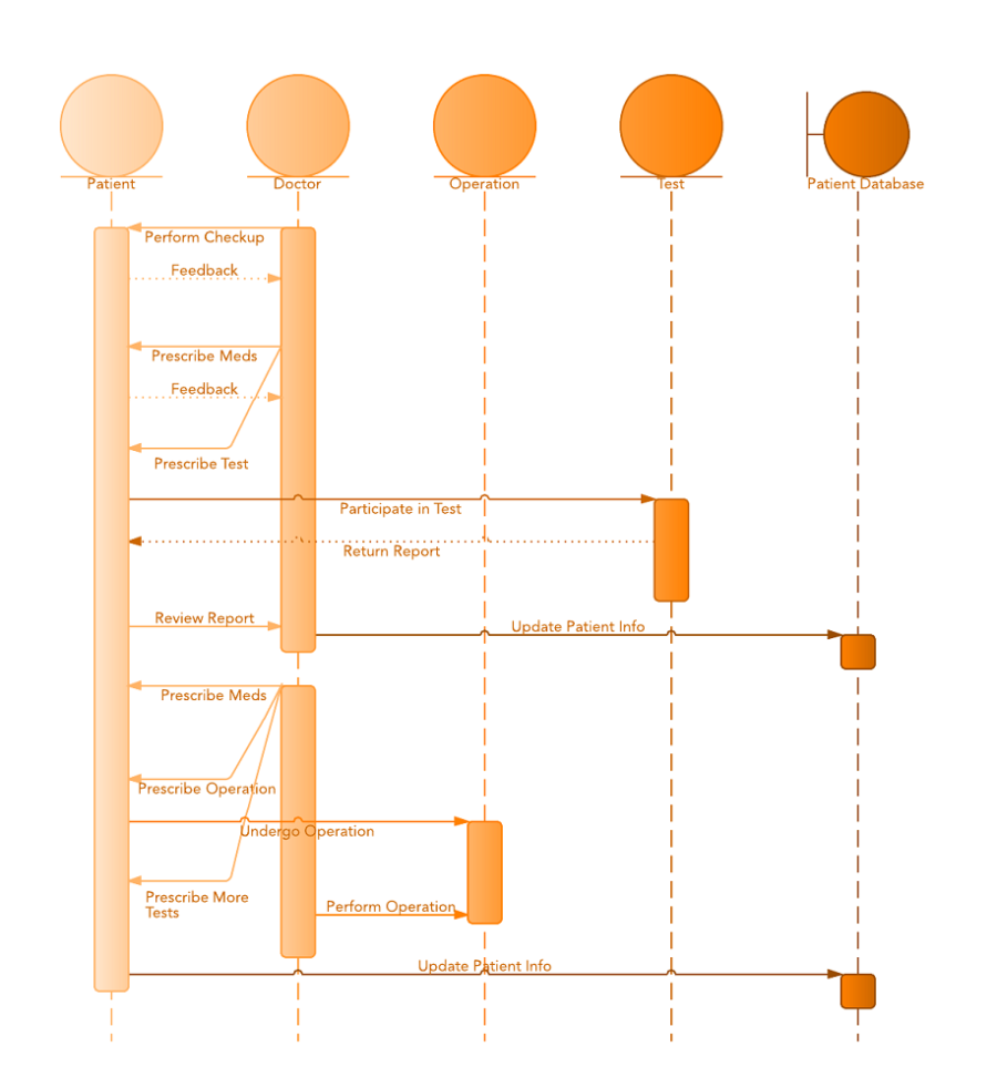
Sequence diagram of a hospital management system
Technology has completely transformed the field of medicine, as it has with most industries. A hospital information system, also known as a hospital information system, helps doctors, administrators, and hospital staff managing all of the activities and information collected at a hospital, including checkups, prescriptions, appointments, and information on the patients and their caretakers. The diagram below provides a simple view of how the primary processes operate with each other over time.
Sequence diagram for ATM systems
An ATM allows patrons to access their bank accounts through a completely automated process. You can examine the steps of this process in a manageable way by drawing or viewing a sequence diagram. The example below outlines the sequential order of the interactions in the ATM system.

How to make a sequence diagram
In Lucidchart, creating a sequence diagram from scratch is surprisingly simple. Just follow these steps:
-
Open a blank document or start with a sequence diagram template from our templates gallery.
-
To the left of the editor, click "Shapes" to open the Shape Library Manager.
-
Check "UML" to enable all of the UML shape libraries or "UML" to enable shapes specific to UML sequence diagrams. Click "Save."
-
Drag the symbols you need from the toolbox to the canvas.
-
Then model the process flow by drawing lines between shapes while adding text.
Dive deeper into this guide on how to draw a sequence diagram in UML for additional insight. In Lucidchart, it's easy to resize and style any element. You can even generate a complete UML sequence diagram from text markup. If you'd like to learn more about UML, check out our "What Is UML" tutorial.